


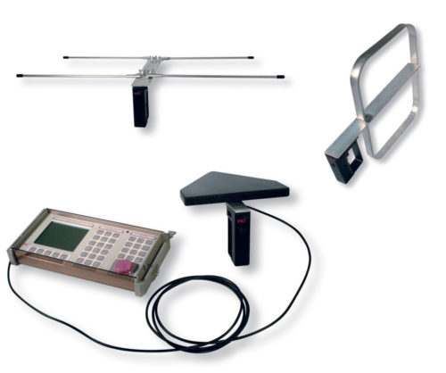
PKI 4390 is designed for mobile use and operation in open space as well as for localisation of transmitters inside. It is the unique solution when high mobility and quick response is essential. The exceptional directional antenna set with integrated electronic compass and data transfer from antenna to analyser provides a classification and localisation of HF signals. This is most important when localising eavesdropping systems.
As soon as a signal is identified the transmitting source can be located by means of bar diagrams and numerical display of the signal level. Besides the displayed information an acoustic signal is audible. The actual antenna alignment is displayed on the monitor and continuously updated by the integrated electronic compass. Additionally the integrated GPS receiver provides necessary position data and hereby ideally supports direction finding.
PKI 4390 works in the frequency range from 9kHz up to 6GHz. 4 active directional antennas are necessary to cover this wide range.
Directional antenna 1: For 9kHz up to 30MHz
Directional antenna 2: For 20Mhz up to 250MHz
Directional antenna 3: For 200MHz up to 500MHz
Directional antenna 4: For 400MHz up to 6GHz
These have to be connected to analyser. A complete scan needs less than 500ms at high resolution. Even sources with very low transmitting power can be identified using the directional antennas due to their extreme low noise level of -30dBμV/m.
| Specifications |
| RF Data | |
|---|---|
| Frequency | |
| Range | 9kHz to 6GHz |
| Phase noise (SSB) | < -100 dBc/Hz (@ 300kHz carrier offset verified at (57,5/2140.5/4500.5 )MHz |
| Reference frequency | |
| Initial deviation | < 1 ppm |
| Aging | < 1 ppm/year, < 5 ppm over 15 years |
| Thermal drift | < 1,5 ppm (-10°C to +50°C) |
| Amplitude | |
| Display range | From displayed average noise level (DANL) to +20dBm |
| Reference level (RL) | -30dBm to +20dBm in steps of 1dB |
| RF input attenuation | 0 to 50dB in steps of 1dB (coupled with reference level) |
| Reference level setting | Set individually from a list or using the “RL Search” function for determining the optimum reference level at a given time |
| Level uncertainty | ≤ 1.2dB (15°C to +30°C) |
| Displayed Average | f ≤ 30MHz: <-160dBm/Hz (noise figure < 14dB) |
| Noise Level (DANL) | f ≤2GHz: <-156dBm/Hz (noise figure <18dB) |
| Basic unit only | f ≤ 4GHz: <-155dBm/Hz (noise figure <19dB) f ≤ 6GHz: <-150dBm/Hz (noise figure <24dB) |
| Displayed Average | f ≤ 3GHz |
| Noise Level (DANL) | f ≤ 4GHz: <- 166dBm/Hz (noise figure < 8dB) |
| With active antenna | f ≤ 6GHz: <- 164dBm/Hz (noise figure < 10dB) |
| Handle, preamp. on (typ). | |
| RL = - 30dBm (input attenuation = 0dB) | |
| 3rd order intermodulation | <-60dBc for two single tones |
| With a level of 6 dB below RG, spaced by 1 MHz or more | |
| Spurious responses (input related) | < -60dBm or RL -60dBm (whichever is worse) and a carrier offset of 1MHz or more |
| Spurious responses (residual) | <-90dBm (RL=-30dBm, input attenuation = 0dB) for 294MHz to 306MHz and 4534MHz to 3486MHz limited to <-85dBm |
| RF input | |
|---|---|
| Type | N-connector, 50 Ohm, female |
| Maximum RF power level | +27dBm (destruction limit) |
| Maximum DC voltage | +/- 50V |
| Return loss | > 12dB (typ.) f ≤ 4.5GHz |
| > 10dB (typ.) f > 4,5GHz | |
| RL ≥ 28 Bm (input attenuation ≥ 2dB) | |
| Operating Modes | |
| Measurements vs. frequency | Spectrum (including Spectrogram) multi-channel |
| Measurements vs. time | Level meter scope (option) |
| Measurements vs. direction finding | Incl. horizontal scan and localisation orientation/position |
| Spectrum | |
| Measurement principle | High resolution spectrum analysis with up to 27000 frequency points |
| Resolution bandwidth | 10Hz to 2MHz (1-2-3-5 steps) |
| RBW (-3dB nominal) | |
| Video bandwidth VBW and RMS detection | 0,2 to 2MHZ (1-2-3-5 steps) or off coupled with selected RBW (VBW = RBW/10…RBW/1000) |
| RMS detection | The effective integration time for forming the RMS value can be defined as T = 0,32 /VBW |
| Filter type | Gaussian shape factor (-60dB/-3dB) 3,8 typical |
| Measurement | |
| Spectrum | Graphical analysis, peak table, channel power |
| Delta spectrum | Display of selected traces relative to the reference trace (ref) |
| Spectrogram | Visual representation of recorded spectra |
| Spectrogram & Spectrum | Visual representation of recorded spectra with simultaneous view of |
| Trace (spectrum) | |
| Act | Clears the previous spectrum and displays the actual measured spectrum |
| Max | Maximum hold function |
| Avg | RMS averaging over a selectable number of spectra (4 to 256) or a selectable time period of 1 to 30 |
| Max Avg | Maximum hold function after averaging |
| Min | Minimum hold function |
| Min. Avg | Minimum hold function after averaging |
| Detector (Spectrogram) | |
| +Peak | Maximum value of all values within an interval |
| RMS | Root mean squared average power of all the measurements within an interval |
| -Peak | Minimum value of all values within an interval |
| All three detectors are used simultaneously for spectrogram recording | |
| Spectrogram recording | |
| Frequency resolution | ≥ Fspan/860 |
| Up to 400 traces (spectrogram lines) | |
| Observation period | Approx.. 4 s up to 40 hours |
| Time resolution | As fast as possible, 10 ms to 5 min (1-2-5 steps) or 6 min |
| Magnifier | Simultaneous display of the selected spectrum and a magnified section of interest (magnification level of 10x or 50x) |
| Level Meter | |
| Measurement principle | Selective level measurement (zero span mode at a tunable fixed frequency) |
| Detector | Peak (hold time = 480 ms) |
| RMS (average time selectable from 480 ms up to 30 min.) Peak & RMS simultaneously |
|
| Resolution bandwidth | 100Hz to 32MHz |
| RBW (-6 dB) | (In steps of 100, 125, 160, 200, 250, 320, 400, 500, 640, 800, 1000, |
| 10MHz, 13.333MHz, 16MHz, 20MHz, 26.666MHz, 32MHz) | |
| Filter type | Steep cut-off channel filter (app. raised cosine) |
| Roll-of factor | 0.16 |
| Video bandwidth (VBW) | 0,01 H to 32 MHz or off coupled with selected RBW (VBW = RBW/1… RBW/10000) |
| Max hold | Available for peak and RMS detectors |
| Noise threshold | Selectable at 0, 3, 6, 10, 15, or 20 dB relative to device noise floor. Measurement values below threshold are shown as “absolute threshold value” |
| Direction Finding | |
|---|---|
| Measurement principle | Selective level measurement (zero span mode at a tunable fixed frequency) Possible parameters and settings as specified under LEVEL METER |
| Antenna direction indication | Numerical display of azimuth, elevation and polarization determined by the embedded electronic compass of the antenna handle |
| Position indication | |
| Outdoor | Instrument position displayed as latitude and longitude determined by the embedded GPS receiver of the basic unit. Optional: graphical indication of the current position drawn on a map |
| Indoor | Instrument position set manually on an editable rectangular room layout |
| Detector | Peak or RMS detection, RMS averaging time: selectable, 0,48 s to 30 min |
| Display modes | |
| Manual bearing | Bar graph and numerical display of the signal level and indication of the direction |
| Horizontal scan | Polar diagram of the signal level vs. antenna orientation, normalized to the maximum signal, automatic direction finding and indication |
| Smart DF localization | Graphical indication of the triangulation results for all measurement positions, accepts measurements being performed by manual bearing or horizontal scan. Display of the estimated emitter coordinates, optional drawn on a map (option mapping) |
| Horizontal scan | |
| Continuous | Every 120 ms the polar diagram is updated with the current signal level and compass data. Start and stop is initiated by key press on the antenna handle. The duration of a scan is limited to a maximum of 4 min. The target azimuth is calculated automatically. |
| Discrete | For every key press on the antenna handle the polar diagram is updated with the current signal level and compass data. At least 3 samples are required for calculating the target azimuth (up to 2000 samples are possible). Useful for longer averaging times. |
| Discrete with max hold | The polar diagram is updated with the max hold signal level and compass data by pressing a key on the antenna handle. Allows determination of the direction even of intermittent signals. |
| SmartDF localization | Shows the vector of target azimuth related to the measurement position. Triangulation results based on several vectors will be calculated and the geo coordinates of the potential transmitter position will be displayed. Coordinates are referenced to the geodetic datum. Signal fading vs. distance can be taken into account for target position calculation. Remotely determined vector data can be added by manual entry. |
| Transmitter table | Used to simplify frequency settings and speed up finding multiple sources transmitting at different frequencies. Tables can be created on-site and include Fcent and RBW. |
| Maps (option) | Display of high-resolution street maps in various zoom levels. OpenStreetMap bitmap tiles can be downloaded from internet free of charge using the PKI map download tool. Map data are stored on micro SD card and then plugged into the card slot for portable use. |
| Scope (Option) | |
| Measurement principle | Selective level measurement (zero span mode at a turnable |
| Resolution bandwidth | 100Hz to 32MHz |
| RBW, (-6 dB nominal) | (In steps of 100, 125, 160, 200, 250, 320, 400, 500, 640, 800, 1000,…10MHz, 13.333MHz, 16MHz, 20MHz, 26.666MHz, 32MHz) |
| Filter | Type: steep cut-off channel filter (app. raised cosine) Roll-off factor 0.16 |
| Video bandwidth (VBW) | 0,01 Hz to 32 MHz or off coupled with selected RBW (VBW = RBW/1..RBW/10000) |
| Measurement | |
| High resolution scope | Measures the actual magnitude Time resolution coupled to 1/RBW (31.25 ns to 10 ms) |
| Long-time scope | Uses selectable detectors to measure the magnitude Sweep time 4 µs to 24 h (resolution ≥ 250 µs |
| I/Q data | Measures the real and imaginary part of the signal I, Q or both (max. 250000 samples each) Time resolution coupled to 1/RBW (31.25ns to 1ms) |
| Detector | +Peak, RMS, -Peak can be selected individually for long-time scope |
| Magnifier | Simultaneous display of the selected spectrum and a magnified section of interest (magnification section of interest (magnification level of 25x or 500x) |
| Duty cycle | Measurement function for the ratio of average power to maximum power (not for I/Q data) |
|---|---|
| Triggering | Free run, single, multiple, manual start, time controlled Programmable trigger level, trigger slope and trigger |
| Multi Channel Power | |
| Measurement principle | Spectrum analysis, followed by channel power evaluation |
| Number of channels | 1 to 500, to be defined on instrument or by PKI tools PC software |
| Channel band width CBW (-3DB nominal) | individually selectable for each channel, from 40Hz to 6GHz |
| Roll-off factor | < 4 *RBW/CBW |
| Applied RBW | Automatic: CBW / 4 (RBW ≤ 20 MHz) Manually: 10 Hz to 20 MHz (1-2-3-5 steps), (RBW ≤ CBW /4) Individual: separately defined for each channel using PKI-tools |
| Channel lists | Automatic creation on the unit or by PC configuration software. Channel name is assigned automatically. User definable channel names (15 characters max.) can be assigned by PC. “Others” summarizes results of all frequency gaps within the list of channels. |
| Detection | Root mean square value (RMS), integration time T = 1/RBW |
| Trace, RBW | see spectrum analysis mode |
| Display/Views | |
| Table | Channel name, corresponding frequency band, measurement result, RBW if set individually for each channel. Sort function according to columns. Selectable evaluation function: distribution of each channel in relation to total amount |
| Bar graph | bar graph for measurement result of each channel Noise threshold selectable at 0, 3, 6, 10, 15, or 20 dB relative to device noise floor, measurement values below threshold are shown as “< absolute threshold value”. |
| General Specification-Basic | |
| Instrument display | |
| Type | TFT color display with backlight |
| Size, resolution | 7 inch (152 mm x 91 mm), 800 x 480 x pixels |
| Interface | USB mini B (USB 2.0) Optical RS 232 (baud rate 115 200) Headphone 3.5 mm TRS, switches off the integrated speaker when connected MicroSD-card interface for maps and export of measurement data, screenshots and WAV |
| Cables, external devices | RF cables are automatically detected (type, frequency response and more), other cables and external devices (e.g. filters) can be defined and selected manually |
| Antenna detection | Directional antennas are automatically detected (type, polarization, consideration of typical antenna factors, preamp gain and frequency response), other antenna parameters can be defined and selected manually |
| Result units | |
| With antenna | V/m, A/m, W/m2, mW/cm2 , dBV/m, dBmV/m, dBA/m, dBμV/m, dBm, dBV, dBmV, dBμV |
| Without antenna | dBm, dBV, dBmV, dBμV |
| Display functions | Y-scale reference: -130dBm, to 40dBm Y-scale range: 20dB, 40dB, 60dB, 80dB, 100dB, 120dB Y-scale auto: automatic scaling |
| Marker functions | For graphical analysis of spectrum, spectrogram, scope, MCP bar graph - single marker or delta marker - peak marker: highest, lower, higher, left, right adjustable peak threshold and excursion |
| Demodulation | |
| Modulation types | AM, FM, LSB, USB (level meter and DF mode) |
| Representation | Instrument speaker or external earphone |
| Squelch | -120dB to -40dB nominal, off |
| Audio recording | Format 16Hz / 16 bit wave file recording (WAV) |
| Fast frequency setting | Frequency setting by selection lists (multi-channel table or transmitter table) or by Fstep |
| Fast mode switch | “Go to: mode” transfers centre frequency or marker frequency and other relevant parameters to the selected operating mode |
| Setups | PKI 4390 can store up to 200 device configurations. Up-/download by configuration software |
| Results storage | |
|---|---|
| Measurement results | ASCII format for further evaluation and import into spreadsheets (e.g. MS-Excel) |
| Comments | Voice comments (wave file format) or text comments (ASCII) can be added to saved results |
| Screenshots | File format PNG |
| Demodulation records | File format WAV |
| Conditional storing (not for DF and scope) | Conditional storing of results exceeding a user definable threshold value with individual storage rates and reset function |
| Time controlled storing (not for DF and scope) | Long term monitoring up to 99 hours. inside the basic unit is a GPS receiver for position detection and an electronic compass as an aid to orient the map northwards |
| Compass /GPS | Inside the basic unit is a GPS receiver for position detection and an electronic compass as an aid to orient the map northwards |
| General Specifications - Basic Unit | |
| Environmental | |
| Operating temperature | -10°C to +50°C with battery 0°C to +40°C with external power supply |
| Humidity | < 29g/m3 (< 93% RH at +30°C) non condensing |
| Compliance | |
| Climatic | Storage: 1K3 (IEC 60721-3) extended to -10°C to +50°C Transport: 2K4 (IEC 60721-3) restricted -30°C to +70°C due to display Operating: 7K2 (IEC 60721-3) extended to -10°C to +50°C |
| Mechanical | Storage: 1M3 (IEC 60721-3) Transport: 2M3 (IEC 60721-3) Operating: 7M3 (IEC 60721-3) |
| Ingress protection | IP 52 (with antenna attached and interface protector closed) IP 67 (stored in the hardcase) |
| EMC EU | Complies with EMC directive 2004/108/EC and IEC/EN 61326-1: 2006 |
| EMC immunity | IEC/EN: 61000-4-2, 61000-4-3, 61000-4-4, 61000-4-5, 61000-4-6, 61000-4-11 |
| EMC emissions | IEC/EN: 61000-3-2, 61000-3-3, IEC/EN 55011 (CISPR 11) class B |
| Safety | Complies with European Low Voltage Directive 2006/95/EC and IEC/EN 61010-1: 2004 |
| Weight | 2,8 kg (basic unit including battery) |
| Dimensions | 213 mm x 297 mm x 77 mm (H x W x D) |
| Power supply, Battery | Lithium-Ion rechargeable battery pack, hot-swappable during operation Operating time: 2,5 hours (nominal) Charging time: 4,5 hours (nominal) |
| External power supply | Input: 9 to 15 VDC Adapter 100-240 VAC / 12VDC 2,5 A |
| Calibration interval | 24 months (recommended) |
| Country of origin | Germany |
| Gereral Specification - Antenna Handle and Antennas | |
| Environmental | |
| Operating temperature | -10°C to +50°C |
| Humidity | < 29g/m3 (< 93% RH at +30°C) non condensing |
| Compliance | |
| Climatic | Storage: 1K3 (IEC 60721-3) extended to -10°C to +50°C Transport: 2K4 (IEC 60721-3) Operating: 7K2 (IEC 60721-3) extended to -10°C to +50°C |
| Mechanical | Storage: 1M3 (IEC 60721-3) Transport: 2M3 (IEC 60721-3) Operating: 7M3 (IEC 60721-3) |
| EMS EU | Complies with European Low Voltage Directive 2006/95/EC and IEC/EN 61326-1: 2006 |
| EMS immunity | IEC/EN: 61000-4-2, 61000-4-3, 61000-4-4, 61000-4-5, 61000-4-6, 61000-4-11 |
| EMS emissions | IEC/EN: 61000-3-2, 61000-3-3, IEC/EN 55011 (CISPR 11) class B |
| Safety | Complies with European Low Voltage Directive 2006/95/EC and IEC/EN 61010-1: 2004 |
|---|---|
| Dimensions (L.W.H) | Handle: 165 x 165 x 43 mm, 470g |
| Weight without cable | Dir. antenna 1: 326 x 255 x 80 mm, 450 g Dir. antenna 2: 285 x 410 x 43 mm, 350 g Dir. antenna 3: 460 x 320 x 48 mm, 400 g 3100/14: 430 x 370 x 42 mm, 380 g |
| Country of origin | Germany |
| Active Antenna Handle (3100/10) with Electronic Compass and Preamplifier | |
| Frequency range | 9kHz to 6GHz Frequency response correction is applied automatically when used in conjunction with the PKI basic unit |
| Preamplifier | Built-in, can be switched off amplification 20dB, noise figure < 6dB |
| Compass | Embedded electronic compass |
| Compass uncertainty | Azimuth uncertainty < 1,5° RMS for tilt < 15° pitch and roll uncertainty < 3° RMS in the range of +/- 30° (RMS means the standard deviation of the specified error) |
| Connection cable to basic unit | RF cable and control cable combined in a flexible tube, length 1 meter |
| RF connector to basic unit | N-connector, male, 50 Ω |
| RF connector to directional antenna | BMA 50 Ω (female on handle side) |
| Antenna connectivity | Antennas can be plugged in with horizontal and vertical polarization. Type of antenna and polarization detected automatically and transferred to basic unit |
| Power supply | From basic unit |
| Mounting | Connecting thread on the underside of the handle for tripod mounting |
| Directional Antenna 1 | |
| Frequency range | 20 MHz to 250 MHz (Typical antenna factor correction is applied automatically when used in conjunction with the basic unit and active antenna handle) |
| Antenna type | Loop antenna |
| Antenna factor | 21dB (1/m) typical @ 200MHz (passive mode) |
| Directional Antenna 2 | |
| Frequency range | 200 MHz to 500 MHz (Typical antenna factor correction is applied automatically when used in conjunction with the basic unit and active antenna handle). |
| Antenna type | Dipole antenna |
| Antenna factor | 21dB (1/m) typical @ 350MHz (passive mode) |
| Directional Antenna 3 | |
| Frequency range | 400 MHz to 6 GHz (Typical antenna factor correction is applied automatically when used in conjunction with the basic unit and active antenna handle) |
| Antenna type | Log-periodic antenna |
| Antenna factor | 18,5 dB (1/m) typical @ 500 MHz (passive mode) |
| Loop Antenna, H-Field | |
| Frequency range | 9 kHz to 30 MHz (Typical antenna factor correction is applied automatically when used in conjunction with the basic unit and active antenna handle) |
| Antenna type | Shielded loop antenna |
| Antenna factor | Passive mode (preamp, off): 66,0dB (1/m) typical @ 100kHz 47,5dB (1/m) typical @ 1MHz 42,0dB (1/m) typical @ f > 10MHz |